Introduction
Field mobile robots are extremely useful for operating in hazardous environments and performing urban search and rescue missions. To enhance mobility in unseen environments, most mobile robots are wirelessly operated. Although mobile robots have much potential in hazardous and hard-to-access environments, wireless connectivity has always been a limiting factor in the full-scale utilization of robots in these scenarios.
Summary of Contributions
Hybrid Mechanism Mobile Robot (HMMR), also known as Hybrid Mobile Robot (HMR), was first developed by Dr. Pinhas Ben-Tzvi during his Ph.D study in University of Toronto.
To meet the requirements of the further research on Semi-autonomous/Autonomous behaviors, my work on this project focused on,
- Mechatronics Components Upgrade , including PCB design, multiple sensors (RGB camera, depth camera, IMU, etc.), computers (microcomputers, single board computer, etc.), wireless communication (Wi-Fi), etc.
- System Architecture Upgrade , integration with Ubuntu OS and ROS.
Overall System Architecture

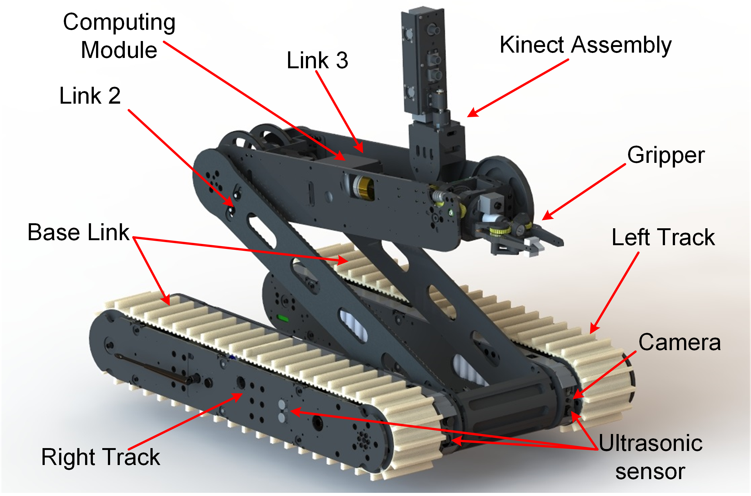
Fig. 1 CAD rendering of the HMMR
Mechanical Design
HMMR is an articulated three-linkage, tracked mobile robot capable of using its manipulation links for locomotion and to traverse large obstacles as shown in Fig. 1. In a retracted form, the overall dimensions of the HMMR are 530mm(W)×630 mm(L)×140mm(H).
The HMMR achieves locomotion using two tracks (left track and right track) which are connected through a shaft, together forming the Base Link (Link 1). Link 3 hosts a 3-DOF two-finger gripper. All the links and modules in the HMMR have individual power supplies and communicate wirelessly, allowing endless rotation in all revolute joints in the HMMR. The end effector can also rotate endlessly inside Link 3 to achieve full pitch/roll rotation.
In each track, there are two lamps (one on the front side and one on the rear side), four ultrasonic sensors (two on the lateral side, one on the front side and one on the rear side), GPS (right track)/IMU (left track), and one camera (rear side of the right track or front side of the left track). In Link 3, there is one 2-DOF mounting platform for a Kinect. Driven by servo motors, the mounting platform can achieve pitch and yaw rotation, which helps the Kinect scan the surrounding environment.

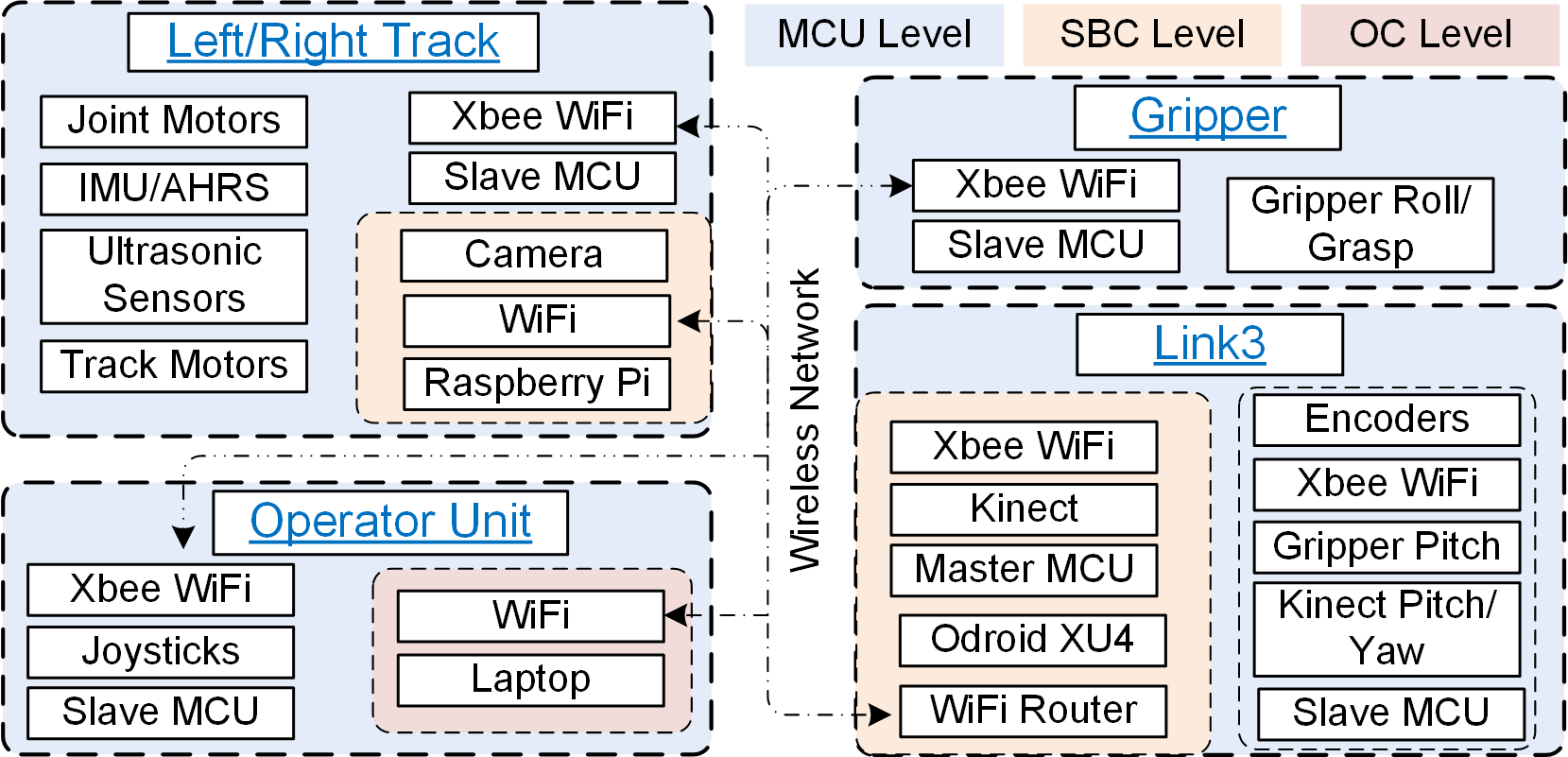
Fig. 2 Updated System Architecture of the HMMR
Mechatronics Design
The mechatronic architecture of the HMMR is presented in Fig. 2. The updated system is proposed to fuse sensor data, send actuator commands, and achieve high-level tasks such as obstacle detection and motion planning. The computing architecture is divided into three computing levels: microcontroller (MCU) level, single board computer (SBC) level, and Operator’s Computer (OC) level.
At the MCU level, a Teensy 3.2 is used as the microcontroller (MCU) in each link. It fetches raw sensor data and sends commands to the actuators. All the subsystems in the HMMR are controlled by dedicated ‘slave’ MCUs. The sensory data and commands are shared among the subsystems over a Wi-Fi network. The MCU mounted in the master board in Link 3 updates status data from the slave MCUs in the HMMR and the Operator’s Control Unit (OCU).
At the SBC level, single board computers (Raspberry Pi Zero), mounted in both the right and left tracks, fetch video data from the rear and front cameras, respectively, preprocess data (filtering noise, undistorting frames), and stream processed data to a local network via Wi-Fi. Another single board computer (Odroid XU4) is mounted in Link 3, working as the central computing unit (CCU), and is connected to the Wi-Fi router via Ethernet, and to the master MCU via USB cable. The CCU fetches HMMR updated data from the Teensy MCUs and video data from the network, and then publishes them via Robot Operating System (ROS). Some high-level tasks are processed in CCU such as floor detection, motion planning, and environment mapping.
The HMMR is remotely controlled by a touchscreen enabled OCU powered by a high performance laptop computer. At the OC level, a ROS based GUI processes 2D/3D vision data received from the HMMR to visualize the robot’s status and the sensed environment (in 2D/3D). The OCU also combines commands received from joysticks with other user interactions through the GUI and sends command packets over a long-range Wi-Fi network.

Fig. 3 Detailed Process of Updating HMMR System
- HMMR with old system before the update
- Disassembling and cleaning
- Updated control board for motors located in the tracks
- New Master control board located in Link 3
- New Slave control board located in tracks
- System check before installation to HMMR
- Camera system check
- New Operator’s Control Unit (OCU) using Jetson TX2 and running Ubuntu and ROS
- Whole system check after installation
- Side view of New Master control board
Related Publication:
- [C1] Ren, H., Kumar, A., Ben-Tzvi, P., "Obstacle Identification for Vision Assisted Control Architecture of a Hybrid Mechanism Mobile Robot", Proceedings of the ASME 2017 Dynamic Systems and Control Conf. (DSCC 2017), Tysons Corner, VA,Oct 11-13, 2017.