Introduction
The ability to track three-dimensional motion is vital in many industrial and academic research applications including machine vision and robotics. Applications such as robot navigation, virtual reality and augmented reality require real time processing and low-latency motion capture systems. Medical applications such as gait analysis, filmmaking, and video development applications require systems with high accuracy to reconstruct the 3D pose of actors or capture subtle movements such as facial expressions. Applications like virtual reality and augmented reality heavily rely on accurate motion tracking while recording the subject in real-time for the construction of a virtual scenario.
Summary of Contributions
LOSA-X is built upon previous generation system: the Linear Optical Sensor Array (LOSA) tracking system. The focuses of my work on this project include,
- Designed a new system architecture to integrate multiple trackers, and upgrade the mechatronics components and PCB design.
- Fused multi-sensor data obtained from deployed trackers and active marker using Extended Kalman Filter (EKF) to provide higher accuracy, sensing volume, and update rates at a lower cost.
- Proposed background illumination removal techniques to estimate and remove background illumination from raw sensor data and isolate the light source of the active marker

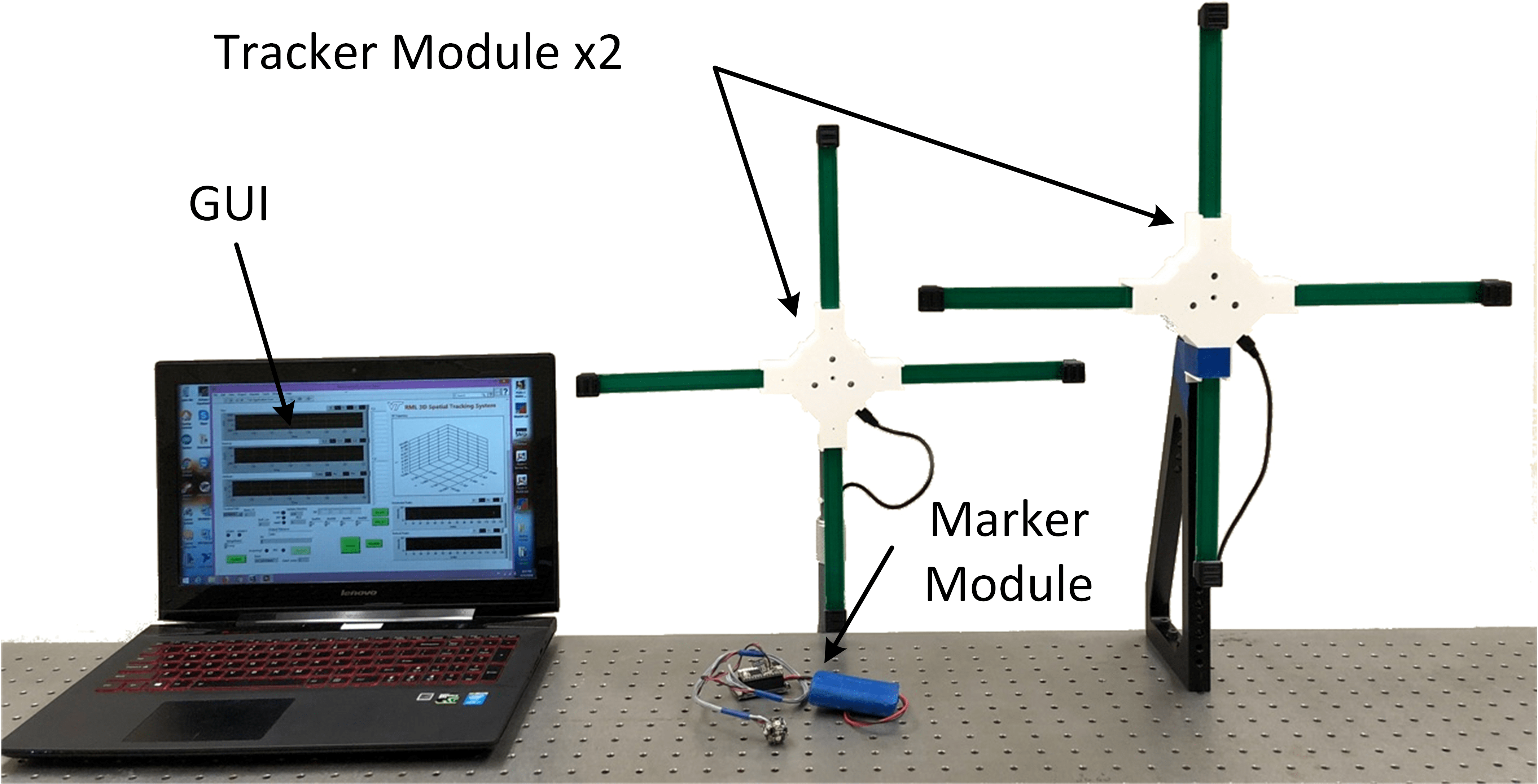
Fig. 1 LOSA-X Motion Capture System
Overall System Architecture
The LOSA-X motion capture system comprises of multiple tracker modules, a multi-LED illuminated active marker module, and a host computer as shown in Fig. 1. Each module is equipped with a Wi-Fi transceiver module to enable high-speed wireless communication amongst each other. With a 9-DOF IMU and unique line-of-light optics, the proposed system is capable of estimating the orientation and position of the active marker with respect the tracker modules.
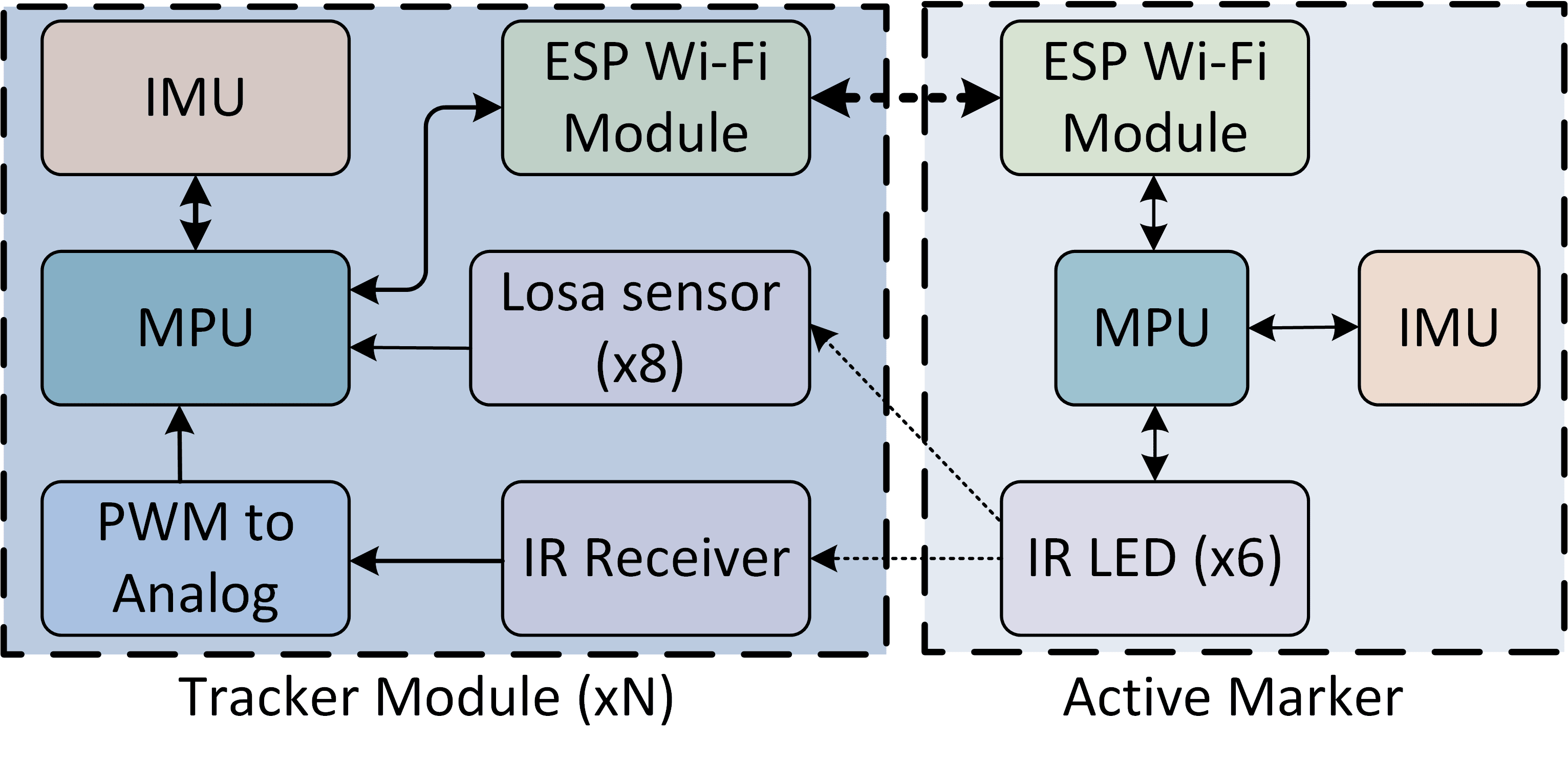
Fig. 2 Hardware Schematic of the LOSA tracking System
The host computer fuses the marker position measurements from each of the tracker modules, along with the inertial measurements from the marker’s IMU to track the position and attitude of the marker with high accuracy and precision. The marker, trackers, and the computer all wirelessly communicate with each other and work in tandem as a single system to estimate the position and attitude of the maker in real-time with high accuracy.
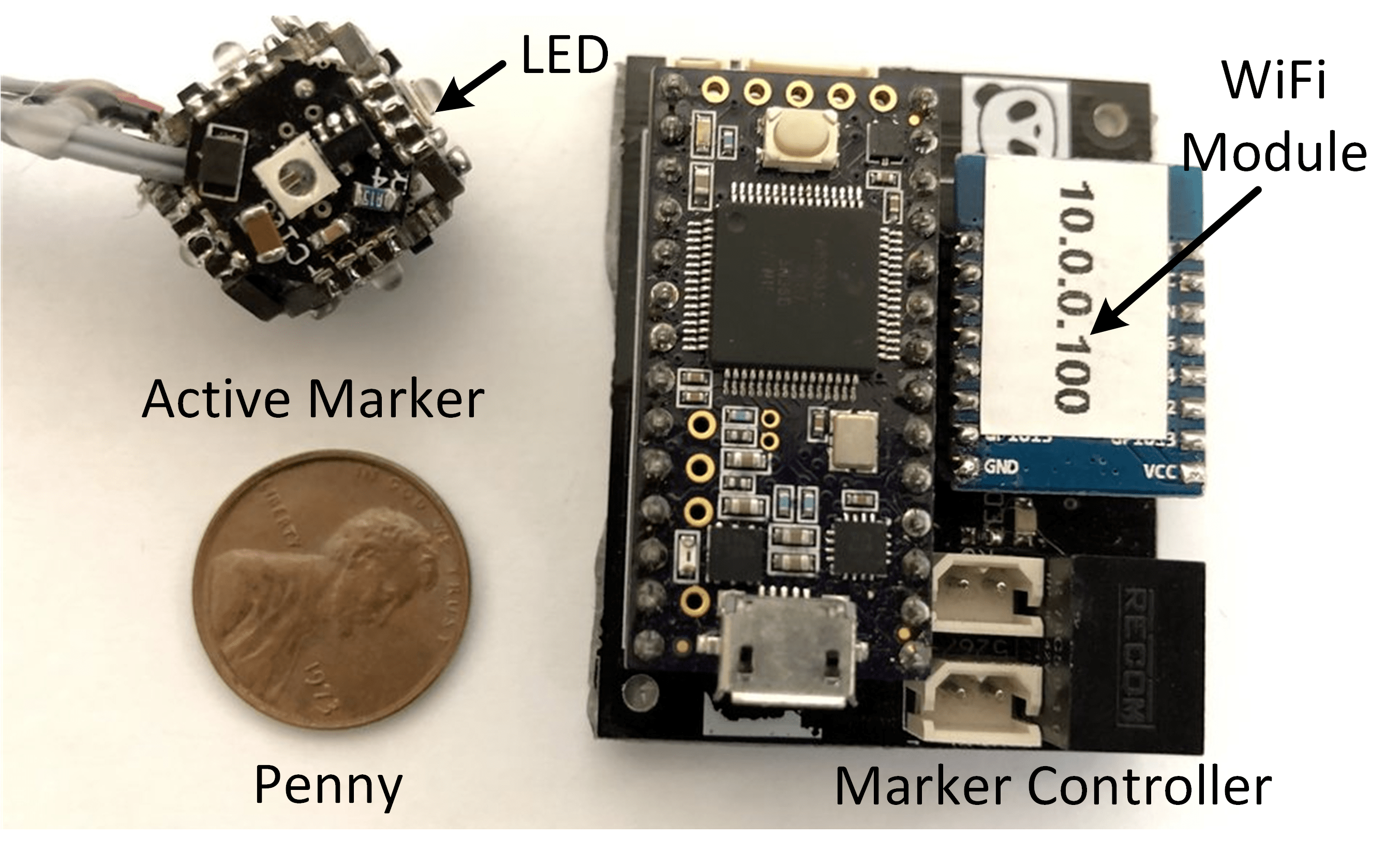
Fig. 3 Active Marker with its Control Board
Each tracker module is controlled using an ARM cortex M4 microcontroller (MCU) mounted on the central computing board. The MCU interfaces with 8 TSL1401R LOSAs (two on each of the four sensor modules), one MPU9250 IMU, and an IR receiver sensor for remote control. The central computing board also hosts an ESP8266 Wi-Fi module (manufactured by Espressif Systems) to enable high-speed communication between the trackers and other systems. Figure 2 shows schematics of the tracker module. Each tracker module is battery-powered (although USB power is possible). The IR (remote) receiver sensor (TSMP6000) is placed at the center of the tracker module to determine the visibility and lighting of the active LED marker. The IR receiver sensor is essentially a band pass filter which responds only to light flashing at high frequencies between 20 and 60 kHz. The receiver responds to flashing light generated by the active marker at this frequency range by returning a pulse width modulation (PWM) output. A multistage passive RC low pass filter is built between the IR sensor and the MCU to obtain the analog signal from the PWM output. The tracker can use this analog signal to detect the presence of a marker.
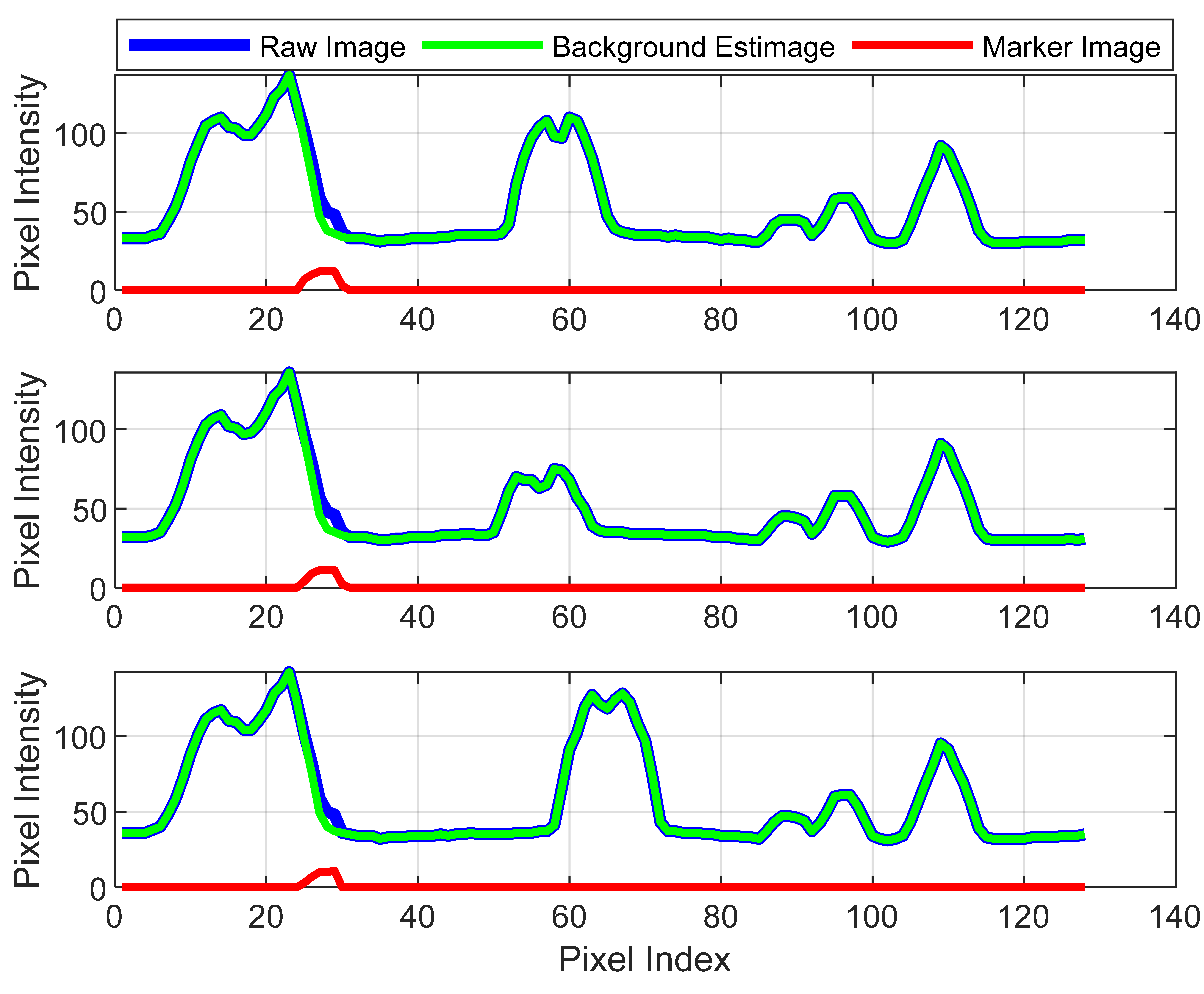
Fig. 4 Dynamic bright background illumination removal
To evaluate the position estimation capability of the proposed system, the motion of the marker was tracked using a two–tracker (namely Tracker1 and Tracker2) LOSA-X system prototype. In the experimental setup, the marker is mounted on a rod hinged on an optical table and constrained to move in plane on a circular trajectory of radius 260 mm with respect to the hinge position. The tracker modules are placed at different locations with respect to the marker module with the position accurately measured using laser range finders. Figure 8 shows three samples of marker images captured while changing the background illumination.
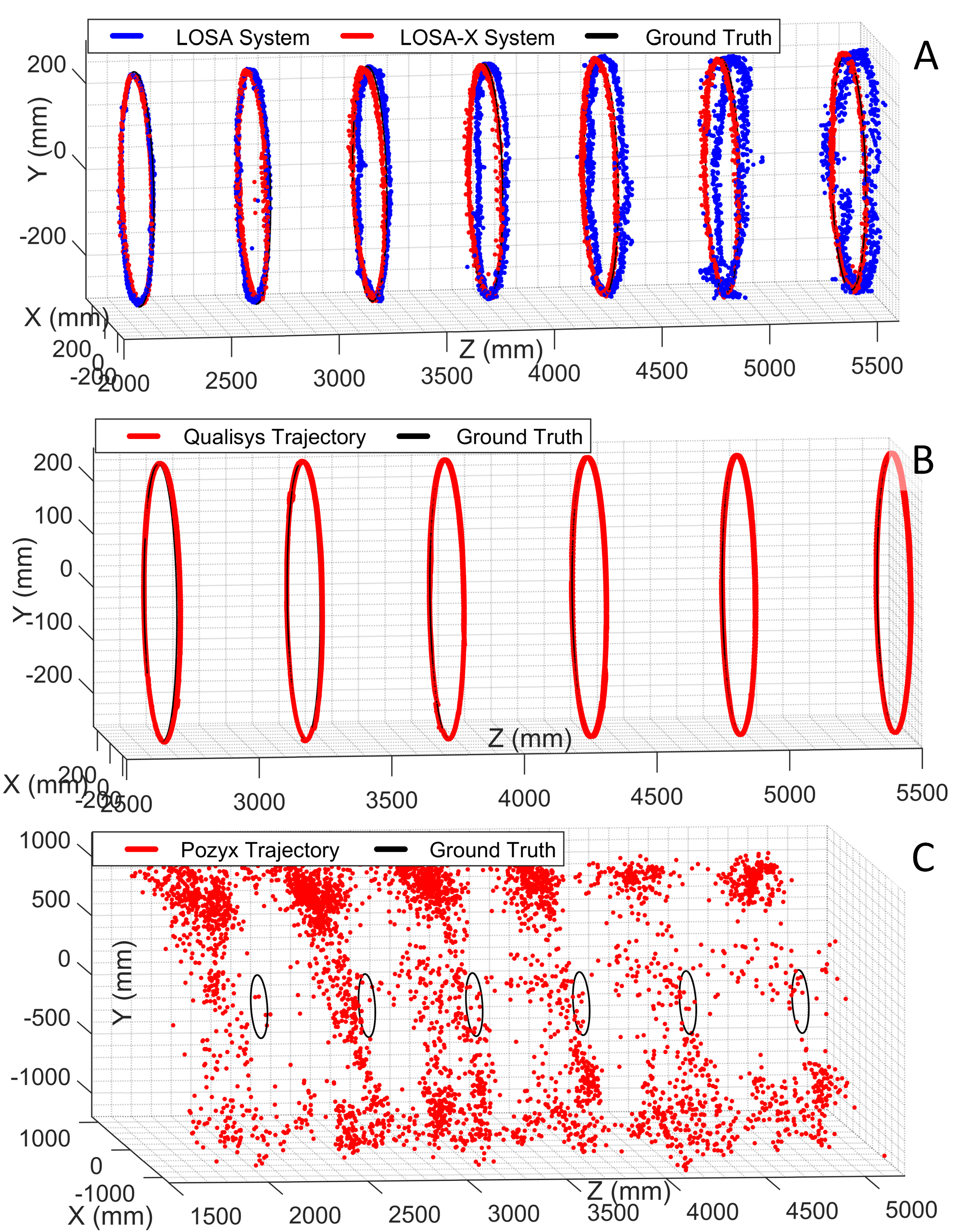
Fig. 5 Position measurement with Pozyx and Qualisys
Figure 5A compares the position estimates from system with the expected trajectory at different operating ranges. Figures 5B and 5C show similar trajectory results obtained from commercially available motion tracking systems Qualisys (in 10-camera configuration) and Pozyx.
Related Publication:
- [J1] Ren, H., Kumar, A., Ben-Tzvi, P., "LOSA-X: Expandable 3D Motion Tracking System", IEEE Sensors Journal, Vol. 19, Issue 9, pp. 3288-3295, May 2019.